Difference between revisions of "Volume 1: Ground Systems"
(Created page with "== Chapter 1: Reconnaissance == Reconnaissance represents all measures associated with organizing, collecting, and studying information on the enemy, terrain, and weather in t...") (Tag: Visual edit) |
(Tag: Visual edit) |
||
| Line 17: | Line 17: | ||
* Unmanned aerial vehicles (UAV chapter in Volume 2) | * Unmanned aerial vehicles (UAV chapter in Volume 2) | ||
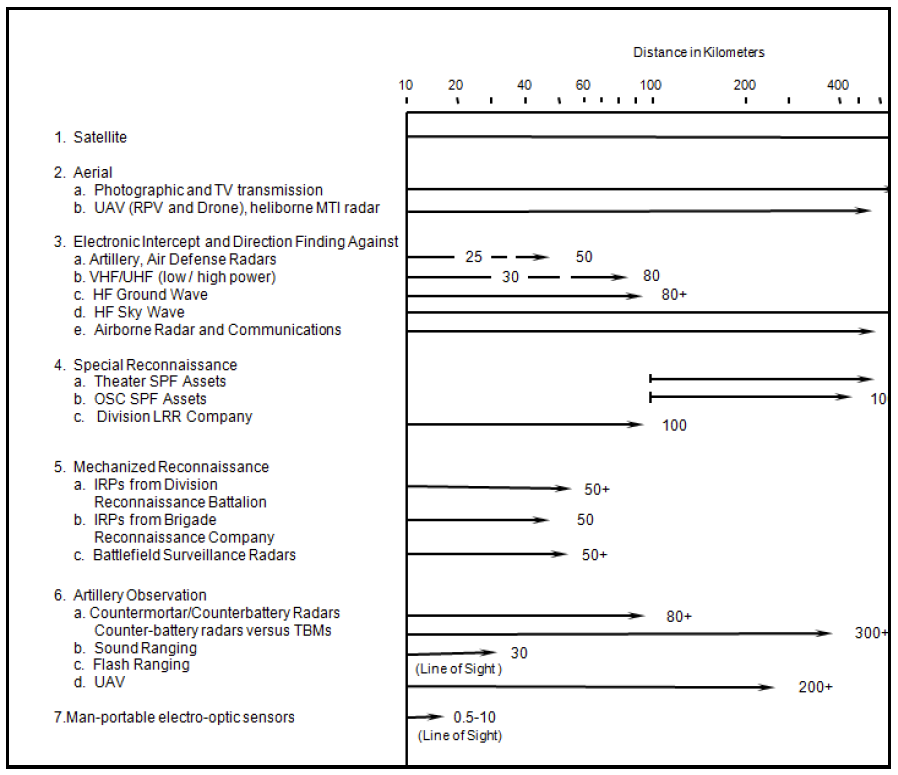
The reconnaissance effort depends upon sensor technologies for location, surveillance, and acquisition. Most units will employ a mix of older and newer systems, with recon vehicles, portable sensors, and man-portable sensors. The most prolific sensor on the battlefield is the human eye. Range is a critical factor. The table below gives general range capabilities. | The reconnaissance effort depends upon sensor technologies for location, surveillance, and acquisition. Most units will employ a mix of older and newer systems, with recon vehicles, portable sensors, and man-portable sensors. The most prolific sensor on the battlefield is the human eye. Range is a critical factor. The table below gives general range capabilities. | ||
| − | [[File:Chapter 1 Effective Ranges of Selected Reconnaissance Assets.png | + | [[File:Chapter 1 Effective Ranges of Selected Reconnaissance Assets.png|frame|561x561px|none]] |
The most prolific reconnaissance discipline is HUMINT reports generated by ground units. Much of this reconnaissance effort consists of tactical recon missions executed by maneuver units in their operational area. Any unit can generate reconnaissance. The OPFOR will exploit civilian information and acquisition assets for reconnaissance purposes. While OPFOR units may operate reconnaissance vehicles, most will have possess the ability to operate dismounted observation posts (OP). These dismounted OPs may possess similar capabilities as vehicle mounted patrol vehicles. The OPFOR will used many types of vehicles for reconnaissance including motorcycles, all-terrain vehicles, or civilian vehicles. The OPFOR will use equipment such as multi-spectral concealment materials, navigation equipment, light-weight laptop computers, and long-range communications/digital transmission systems while conducing reconnaissance. | The most prolific reconnaissance discipline is HUMINT reports generated by ground units. Much of this reconnaissance effort consists of tactical recon missions executed by maneuver units in their operational area. Any unit can generate reconnaissance. The OPFOR will exploit civilian information and acquisition assets for reconnaissance purposes. While OPFOR units may operate reconnaissance vehicles, most will have possess the ability to operate dismounted observation posts (OP). These dismounted OPs may possess similar capabilities as vehicle mounted patrol vehicles. The OPFOR will used many types of vehicles for reconnaissance including motorcycles, all-terrain vehicles, or civilian vehicles. The OPFOR will use equipment such as multi-spectral concealment materials, navigation equipment, light-weight laptop computers, and long-range communications/digital transmission systems while conducing reconnaissance. | ||
Revision as of 20:50, 21 July 2017
Contents
Chapter 1: Reconnaissance
Reconnaissance represents all measures associated with organizing, collecting, and studying information on the enemy, terrain, and weather in the area of operation. Aggressive, continuous reconnaissance allows the timely accomplishment of combat missions with minimum losses. Poor reconnaissance can lead directly to failure.
The OPFOR term that addresses the totality of reconnaissance activities is RISTA (reconnaissance, intelligence, surveillance, and target acquisition). Therefore, RISTA DOES NOT equal the US term, C4ISR (command, control, communications, intelligence, surveillance, and reconnaissance). For information on OPFOR command and control (C2), see Chapter 9.
The OPFOR commits significant resources to reconnaissance. Prior to hostilities, the OPFOR will already have developed an intelligence picture and expected military courses of actions. While the OPFOR practices similar intelligence and reconnaissance disciplines (HUMINT, SIGNINT, IMINT, etc.) as the US, the OPFOR conducts RISTA with different assets, focuses, and methodologies. Reconnaissance platforms must be able to operate in all spheres: ground, surface, below surface, air, space, naval, and littoral areas. The OPFOR fields reconnaissance assets at all echelons and products derived from those assets are used for actions on the battlefield.
This chapter describes ground maneuver forces and specialized ground troops (special purpose forces-SPF) reconnaissance assets. The most basic sensors are lasers/optics/electro-optics used by infantry units (see Chapter 2). When linked with a radio, these basic sensors can be used for unit reporting and other HUMINT reports. There are also dedicated reconnaissance assets with data sheets in other chapters.
- Aerial reconnaissance (Rotary-Wing and Fixed Wing aviation chapters in Volume 2)
- Air defense reconnaissance, early warning, and target acquisition (Air Defense chapter in Volume 2)
- Artillery target acquisition (Artillery chapter)
- Engineer reconnaissance (Engineer chapter)
- NBC reconnaissance (Chemical chapter)
- Signals reconnaissance (Information Warfare chapter)
- Unmanned aerial vehicles (UAV chapter in Volume 2)
The reconnaissance effort depends upon sensor technologies for location, surveillance, and acquisition. Most units will employ a mix of older and newer systems, with recon vehicles, portable sensors, and man-portable sensors. The most prolific sensor on the battlefield is the human eye. Range is a critical factor. The table below gives general range capabilities.
The most prolific reconnaissance discipline is HUMINT reports generated by ground units. Much of this reconnaissance effort consists of tactical recon missions executed by maneuver units in their operational area. Any unit can generate reconnaissance. The OPFOR will exploit civilian information and acquisition assets for reconnaissance purposes. While OPFOR units may operate reconnaissance vehicles, most will have possess the ability to operate dismounted observation posts (OP). These dismounted OPs may possess similar capabilities as vehicle mounted patrol vehicles. The OPFOR will used many types of vehicles for reconnaissance including motorcycles, all-terrain vehicles, or civilian vehicles. The OPFOR will use equipment such as multi-spectral concealment materials, navigation equipment, light-weight laptop computers, and long-range communications/digital transmission systems while conducing reconnaissance.
Questions and comments on reconnaissance for specific equipment should be addressed to the respective chapter POC. Questions concerning this chapter should be addressed to:
RISTA Key Technology Trends
Mr. H. David Pendleton DSN: 552-7946 Commercial (913) 684-7946
mail address: [[1]]
RISTA Key Technology Trends
Military forces continue to field new RISTA systems and upgrade old legacy systems. These systems can be found in both reconnaissance, tactical, and fir support units.
| System
Category |
Technology Trend | Vol/
Page |
System
Example |
Ref
Page |
| Ubiquitous Handheld RISTA
System |
Remote electronic optics (EO)/3d generation thermal sight, 30x zoom precise location, video
link, & graphic net |
V1/1-17 | Sophie MF | V1/1-32 |
| EO bionics with forward looking infrared (FLIR) camera, laser rangefinder (LRF), and
goniometer for precise target location |
V1/1-19 | ADAD | V1/1-23 | |
| LADAR optical augmentation scans & detects
enemy weapon sights |
V1/1-21 | Mirage 1200 | V1/1-21 | |
| Robotic hand-thrown camera with PDA display,
& robot/ball mount |
V1/1-25 | Macroswiss | V1/1-18 | |
| Camera grenade (rifle, RPG, AGL) remotes in-
flight image to display |
V1/1-25 | SPARCS | V2/4-8 | |
| RISTA
Dismount Team Assets |
Man-portable II camera net to display monitor
& alert system |
V1/1-17 | Nighthawk | V1/1-18 |
| Site spy cameras with remote-display images
on monitor |
V1/1-18 | NG-30 | V1/1-17 | |
| EO Laser target designator guides laser homing
round to 10+ km |
V1/1-20 | DHY-307 | V1/1-20 | |
| Man-portable radar with 24 km range and LPI
frequency |
V1/1-22 | Squire | V1/1-22 | |
| Multi-sensor unattended ground sensors with
remote monitor display |
V1/1-24 | CLASSIC 2000 | V1/1-24 | |
| Hand-launch UAVs/micro-UAVS for infantry,
SPF, RISTA, AT, etc. |
V1/1-26 | Zala 421-08 | V2/4-6 | |
| Masted 50+x EO, 3d generation thermal sights
& other sensors for real-time nets |
V1/1-6 | ATM | V1/4-9 |
| RISTA
Vehicles |
Integrated weapons with sensor pods for
combat reconnaissance vehicles |
V1/1/6 | BRM-3K | V1/1-11 |
| Mast-mounted motorized LPI radars & real-
time digital transmission |
V1/1-7 | HJ-62C | V1/1/13 | |
| Remote add-on turrets & radar modules for
vehicle conversion |
V1/1-7 | Stalker | V1/1-7 | |
| Aerial RISTA Systems | Powered airship or aerostat with video camera
or other sensor arrays |
V1/1-23 | TAOS/Sky Media Pro | V2/7-2 |
| Helicopter/weapon-launch UAV munitions for
real time intel/targeting |
V1/1-26 | R-90 | V2/1-8 | |
| Helicopters & FW with real-time MTI; synthetic
aperture radar |
V2/2-21 | Horizon | V2/2-21 | |
| Other RISTA Assets | INFOWAR, UAV, aerial & HUMINT assets
tactically linked & fused |
V1/1-7 | HJ-62C | V1/1-13 |
| Handheld & embedded GNSS receivers for in-
view displays |
V1/1-14 | Magellan GPS | V1/1-14 | |
| EO laser RF weapon sights with 3d generation
day & night capability |
V1/1-14 | IS-2000 | V1/2-30 | |
| Acoustic sensors quickly detect vehicles,
weapons & aircraft |
V1/1-21 | HALO | V1/1-21 | |
| Trip-wire charges, mines, or sensor-fused
grenade launchers |
V1/1-23 | AJAX | V1/1-23 | |
| Artillery/aerial-delivered & hand-emplaced UGS
display in intelligence net |
V1/1-24 | BSA | V1/1-24 | |
| Weapon launched sensor munitions for aircraft
& artillery |
V1/1-26 | R-90 | V2/1-7 | |
| Laptop display data transmission systems, encryption, and satellite communication
(SATCOM) |
V1/1-30 | Kredo-M1 | V1/1-30 |
Reconnaissance Vehicles
The OPFOR conducts continuous and pervasive reconnaissance activity in all phases of military operations. To accomplish their reconnaissance, the OPFOR uses a variety of vehicles based on the enemy threat and the mobility desired. The spectrum of reconnaissance vehicles range from old systems ill-suited for modern requirements to mobile, lethal, and survivable systems equipped with complex sensor arrays and communication equipment. Some vehicles may work alone or as part of a patrol.
The vehicle most used for reconnaissance is an unarmored 4 X 4 wheeled rive tactical utility vehicle or TUV (see the Infantry chapter for examples). The US M151 or Jeep was originally designed as a reconnaissance vehicle and many countries still favor a similar system due to their small size, speed, and maneuverability in a variety of terrain. Some countries have upgraded their reconnaissance vehicles to something similar to the US HMMWV or British Land Rover.
Reconnaissance vehicles are designed or other vehicles are modified to fit the role desired, force requirements, and the terrain in which the vehicle needs to operate. The vehicles may be unarmed except for small arms carried by the personnel in the vehicle or other larger weapons such as a machine gun or automatic grenade launcher (AGL) may be mounted on the vehicle. Many TUV chassis are poorly suited to adding additional armor for protection of the crew. The additional weight compromises the other positive aspects of the vehicle.
The armored scout car is sometimes better suited for reconnaissance than the TUV. These wheeled vehicles offer good road mobility, and better all-terrain off-road mobility than other vehicle types. The vehicle can be based on a truck, armored personnel carrier, or indigenous chassis to handle the added armor requirements while maintaining good mobility. Many of these vehicles may resemble a TUV, but are designed from the ground up for reconnaissance missions. The armor is often light and the wheels are vulnerable to nearly all weapons. Other improvements may be amphibious capability such as with the French VBL and VBR and larger caliber weapons. Examples of these vehicles include the British Fox, Hungarian FUG-66, and Russian BRDM-2.
In heavy combat or when a larger number of soldiers is needed, the OPFOR will often use modified Infantry Fighting Vehicles (IFV) or Armored Personnel Carriers (APC) as a reconnaissance vehicle. Other countries have produced specialized combat reconnaissance vehicles (CRV) designed to operate ahead of the forward line of troops (FLOT), not to initiate combat, but survived if attacked. These CRVs often sacrifice space for soldiers to gain increased mobility, additional sensors, or increased C2 capacity. Many CRVs use tracks instead of wheels, but the wheeled vehicles have amphibious capabilities the tracked vehicles do not. Examples of CRVs include the Russian BRM-3K, the British Scimitar, and the Austrian Pandur RECCE vehicle.
A newer generation came about with the addition of mast mounts and multi-sensor suites to create a sensor reconnaissance vehicle. These vehicles are not designed to operate forward of the FLOT, but behind the lines using cover while providing continuous data to ground forces. These vehicles feature powerful multi-sensor arrays using masts from five to 10 meters high provide longer-range surveillance with less vulnerability to enemy fires. Most of these sensor vehicles are built on an IFV or APC chassis provides the space for three to five work stations. These vehicles can also serve as an intelligence coordination and analysis center. These vehicles are likely to move less often than a CRV. Examples of these sensor reconnaissance vehicles include the Czech Snezka and Chinese Type 85 with HJ-62C radar. There are also sensor vehicles available for specific branches such as the Russian PRP- 3//PRP-4M for artillery units and the Russian Sborka for air defense units.
Many countries are not using their limited defense dollars not on producing new reconnaissance vehicles, but on improving the sensor suites and mounted them on other vehicles such as the Israeli Rafael Stalker or the French VBL. Some countries are going as far as putting sensors on motorcycles or all-terrain vehicles. See the Infantry chapter for various types of these vehicles are available.
Since reconnaissance forces often operate far away from other friendly units, they need to defend themselves. Some countries have developed vehicles for such purpose with enough firepower, but still can complete the reconnaissance requirements. Examples include the British Saladin Armored Car and the Austrian Pandur Fire Support Vehicle. The main guns on thse vehicles can range from 57 mm to 105 mm on the South African Rooikat. These vehicles are often modified versions of a basic IFV, APC, or other armored vehicle modified to make the vehicle most suitable for reconnaissance vehicles. Some of the more common reconnaissance vehicles are on the following data sheets.
Sensor Technologies for Tactical Ground Forces
Reconnaissance units use a mixture of high and low technologies. As noted in TC 7-100.2, Opposing Force Tactics, forces may perform tactical reconnaissance using designated reconnaissance units/soldiers or maneuver unit soldiers. Sensors span an increasing wider segments of the electromagnetic spectrum while integration C2, navigation systems, data processing, and fusing technologies. Developers offer more compact packages, platforms, sensor integration, and mobility systems for greater situational awareness, better operational security, and shorter response time than ever before.
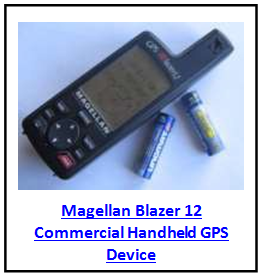
Reconnaissance starts with location and navigation. Instruments include survey instruments (i.e, Bulgarian PAB-2A theodolite), aiming circles or goniometers, GPS receivers, maps, compasses, terrain data, and inertial guidance systems. Commercial equipment such as the Magellan handheld GPS units are sufficient for most forces. Other more advance equipment such as navigation data for laser rangefinders (LRF) and improved communications with digital interface ensure precise navigation.
The primary battlefield sensor is still the human eye, but human vision receives much help. Weapons sights are often used. See the Infantry chapter for day and night weapon sights. Almost all reconnaissance forces use optics such as sights, binoculars, or telescopes to increase viewing capacity. Most of these sights operate in the visual light (0.4-0.75 µm) electro-magnetic (EM) spectrum. Binoculars can vary in features and
magnifications and usually zoom from 7-12 (x) power. For longer-range day acquisition, the OPFOR uses spotting telescopes (Celestron and Swarovski models) with 60 x zoom capability. Other features could include anti-fogging lens coatings, camouflage netting, tripods for better stability or binocular periscopes (German RWDL) for covert viewing.
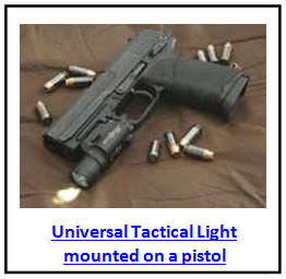
Night-time observation systems which operate in the visual band spectrum are all daylight observation systems similar to the human eye and therefore require visual light illumination to see. The Infantry chapter discusses the capability of using starlight, moonlight, or street lights to enable the average soldier to see greater distances. Illumination support equipment includes spotlights, flashlights, or pyrotechnics (grenades, illumination rounds) to bring light to dark spaces. Specialized devices are available, such as the Universal Tactical Light, which can be mounted on weapons and is located near the weapon’s trigger. Fires or other improvised lighting offer illumination support. To ensure operational security, the OPFOR will usually not use artificial illumination until the fire fight is underway.
Reconnaissance personnel on today’s battlefields have increased their use electro-optical (EO) systems to convert an image into a digital electronic signal that is sent to a display circuit (i.e., photocathode tube or micro-channel plate) for viewing. While optical zoom lens are still critical, EO cameras require almost no focal length or mirrors reducing their size and bulk. Polymers and composite material produce ergonomic devices that are easier to hold with image processing/transmission capabilities for rapid exploitation and dissemination. Zoom capacity can reach 84 x or more allows rapid detection at 10 km or more in distance for selected targets. Day and night EO technologies include TV cameras can convert video imagery into an RF signal to transmit it to a receiver/display unit. Tripod-mounted or aircraft sensor pods can acquire targets at 10-30+ km in distance. Larger systems allows vehicles and aircraft to mount sensors with even longer ranges, better resolutions, and longer transmission ranges.
| ELECTRO-MAGNETIC SPECTRUM AND SENSOR TECHNOLOGIES | |||
| Light Band | Alternate Name | Microns | Technologies |
| Ultraviolet | UV/Black Light | 0.01 – 0.40 | Mercury Arc |
| Visible Light | Daylight | 0.40 – 0.75 | Eye, Optics, TV, Charged- Coupled Device (CCD) |
| Near Infrared | NIR | 0.75 – 1.30 | CCD, Image Intensifiers (II), Active IR |
| Shore-Wavelength IR | 1.30 – 3.00 | Active IR | |
| Mid-Infrared | Mid-Wavelength IR | 3.00 – 6.00 | Thermal |
| Far Infrared | Long-Wavelength IR | 6.00 – 15.00 | Thermal/Forward Looking Infrared (FLIR) |
All night-time observation systems that operate outside of the visual spectrum are EO systems. CCD offers some capability during dawn and dusk and periods of adverse weather that create low light levels. Sub-component improvements offer night vision devices that are clearer, more compact, more resistant to glare, require less power, more time between service, with new features including laser pointers, better zoom, greater magnification, or electronic zoom capability. Commercial grade viewers offer affordable alternatives to military systems. Electronic zoom (EZ) can expand images to multiply the optical zoom by a factor of 3-8 x resulting in magnification of 60-100+ x in affordable systems. This doubles or triples the acquisition range, but could reduce image clarity in the highest EZ modes.
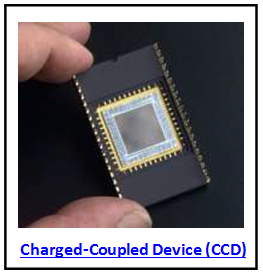
One inexpensive digital technology is the charged-coupled device (CCD) used in many video camcorders and some cameras operate in the near IR
(0.75 – 1.3 µm) band. These CCDs generally lack ability to see in absolute darkness, but most (Bushnell Night- Hawk) offer superior day vision, video capability, and can be used in “low-light-level” (LLL) conditions. There are some 20-80 x CCD binoculars claim a day acquisition range of 10 km (8 km for man-sized targets).
The following table notes the evolution and variety of viewing sensors meld EO with other technologies used by reconnaissance as well as other ground force units.
| EVOLUTION OF OPTICS AND EO SENSORS: GROUND FORCES APPLICATIONS | ||
| Surveillance and Observation | Added Technology | Weapons Target Acquisition |
| Binoculars Theodolites
Telescopes |
Optics (Lenses and Reticles) | Day Sights (Telescopes & Collimators) |
| Day/Night Viewers Digital Cameras Video Recorders | Electro-Optics | Day Sights Night Sights |
| Laser Rangefinders (LRF) | Laser Technology | Laser Aiming Sights & Pointers |
| Laser Illuminators “Radars” | FCS Optical Augmentation | |
| Digital Survey Sets | Navigation/Unit Location
(GPS, Computer, LRF, Goniometer) |
LRF Fire Control Systems |
| UAV
Drone Remotely Piloted Vehicle (RPV) |
Rocket Motor/Airframe | Fiber-Optic Guided Missiles Attack UAVs
Laser-Homing Missiles |
| Micro-UAV; Canister Launch UAV Artillery/Rocket Launch UAV
TV Recon Grenades, Projectiles, or Rounds |
Artillery/Grenade/Canister Launcher | Attack UAVs
Laser-Homing Munitions, Rockets Laser Target Designators |
| Unattended Ground Sensors (Cameras)
Multi-Sensor Pods (Vehicles/UGS) Passive IR (Autotracker) Alerters |
Remote Cameras/Acoustics (Motor Drive Actuator/Controls) | Side-Attack Mine Sensor Units
Unattended Anti-Tank Grenade Launchers (ATGL) Sensors |
| Unmanned Ground Vehicles (UGVs) | Robotic Cameras (Robotic Chassis) | UGVs with guns, ATGLs, or ATGMs Robotic Mines |
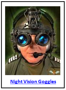
Night Infrared Viewers operate in the 0.75 – 2.00 µm band employ active light sources such as IR spotlights and this technology is easily detectible by adversaries with night vision systems. Therefore, the use of this technology has declined as the passive mode range is limited creating limited practical value. Passive night technology such as II can be found in the Infantry chapter. This technology is now in its 3rd generation, but some companies are claiming a 4th generation technology. This technology continues to expand due
to requirements from hunters, police, and the military. Night vision goggles (NVGs), such as the Malaysian NG-30, allows for hands-free operations such as for driving with many affordable ($200+) for the Nighthawk. The cheaper NVGs, however, may not offer as many features as those designed specifically for the military. Some cameras fuse II and CCD together for effective and affordable day/night use. Many night scopes, night views, and NVGs are not weapon’s sights, but can be used to improve accurate firing. These devices can be used to detect targets or queue new targets for weapons. An assistant with an NVG could use a visual light pointer to designate targets for the weapons operator to engage.
A newer night vision technology called thermal imagery (TI) is now challenging II in popularity as it surpasses the former in range and resolution. TI can “see” any object with temperature different than the background objects so TI can operate in absolute darkness. TI, however, does possess some limitations.
- Shapes are sometimes converted into images not readily recognized based on the human’s visual frame of reference.
- At certain times of the day, the temperature changes may alter shapes or render objects invisible.
- Lack of heat from selected targets means the TI may not see objects in the foreground or background, which helps to provide contrast and context to the observer.
- Generally TI are bulkier than II and require bulky and noisy coolant bottles or power supplies.
- TI sensors are usually more expensive than II sensors.
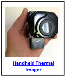
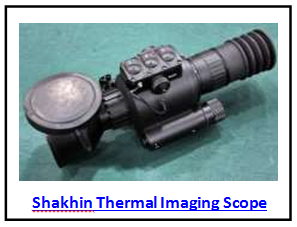
TI does offer several significant advantages as TI is particularly sensitive to temperatures of warm-blooded animals, vehicle engines, solar-heated metal surfaces, and running gear from moving vehicles. Even after a vehicle stops, the residual engine heat renders a clear TI image for an hour or more. Second, TI usually provides faster and easier detection than II. Many TI systems use cameras operating in the mid-IR band (3.00 – 6.00 µm) with ranges up to 2 to 3 km. FLIR, operating in the far-IR (6.00 – 15.00 µm) band, offers superior clarity and range (3-4 km) for most applications making it the preferred technology. Due to increased production and competition, the cost has declined so TI is affordable for priority weapons such as ATGM launchers, tanks, and IFV. In Tier 1 and Tier 2 forces, TI is commonly used in reconnaissance vehicles.
Over the years, TI has improved so it can be categorized by generation like II. The current proliferation of mercury- cadmium-telluride and SPRITE detector staring arrays increased ranges to 5+ km while improving the discrimination of the images. A recent development is the uncooled TI
that eliminates the bulky coolant bottle. An even more recent 3rd generation system combines II and FLIR to fuse them into one clear image. Reduction in the size of parts including microcircuits and imagers have produced portable TI viewing systems. In Tier 1 and 2 reconnaissance units and selected other units, key sensors and dismounted personnel will possess Sophie thermal binoculars with the II/FLIR upgrade. Some reconnaissance units may employ ATGM thermal sights for battlefield surveillance. The larger the system, the longer range and better clarity of most IR systems.
The miniaturization of camera technologies through CMOS
(complementary metal-oxide semi-conductor) transistors and the spread of commercial products offer fertile ground for new military reconnaissance applications. EO systems, such as the Bushnell Nighthawk CCD Viewer and Digital Imaging System 22 x 60 spotter scope offers video output could be transmitted to computers or goniometer systems. These cameras allow remote viewing options. “Nanny-cams” such as the XCam2 or British Spy Vision can monitor close-in areas such as urban streets and then transmit the images. Tactical applications could include hand-thrown cameras such as the Macroswiss. Other off-the-shelf technology such as digital cameras, camera cell phones, and binocular CCD imagers possess military applications.
Lasers are important for measurement, location, and target acquisition. The most important of these is the laser rangefinder or LRF. The LRF is used to measure distances to targets, surveying, or self-location—all important in firing both direct and indirect fire weapons. Many fire control systems on crew-served weapons or on combat vehicles include an in-viewer LRF that provides data into the FCS computer for target acquisition. Dismounted
soldiers can used a hand-held LRF as as the Leica Vector or Aselan LH-7800 binoculars can precisely measure ranges out to 10 km. Some binocular LRFs, such as the Eloptro LH-40C and Russian 1D18, can range targets to 20 km limited only by line-of-sight and the subject’s size. Some of these hand-held systems such as the Bushnell Lytespeed with a 1 km range cost less than
$300.
One of the biggest benefits of lasers integrated into EO systems is increased responsiveness as the optics, EO, acoustics, radars, and other sensors can provide accurate location without the need for a second azimuth to solve an intersection problem. The time required to obtain the second azimuth could allow the target to escape if they are moving. Targets can be precisely located and engaged with only one azimuth, a laser snap, and a simple ballistic computer.
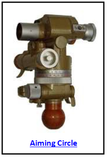
The goniometer uses LRF technology and is similar to the old aiming circles used in artillery and mortar units to fire indirect fire. The goniometer surveys itself into position on a tripod base with an azimuth viewer. Most
goniometers are illuminated for night-time use, carry a GPS mount, and a simple computer (or programmable calculator) to determine self-location, directions, and elevations/deflections. Some goniometers are linked to a digital transmission system or have one built right into the system. A binocular LRF could be mounted on top to sight and range objects, targets, and registration points. Night sights can be added for 24-hour operations. The system can be referred to as a goniometer system, a fire control system (Vetronix Mortar FCS-MORFIRE), a forward observer system or FOS (OIP Delft), an observation station (Leica Digital), a targeting system (Sure Strike), or other names. The modern goniometer-based LRF FOS for the OPFOR is the SG12 with GPS, Leica 21 LRF with 12 km range, thermal night sight, computer interface, and digital data transfer. The entire time to emplace the system is under two minutes.
An aiming circle can be used for similar purposes with the same accuracy, but only when all of the separate components (LRF, GPS, computer, digital transmission system) are present. Often, a goniometer-based system can be more responsive, move more quickly, and produce greater accuracy than an aiming circle. Any OPFOR aiming circle should be regarded as the base for an observation system. Most dismounted forces worldwide will use an aiming circle or goniometer-based system. Due to its size and ability to be broken down, the goniometer system is portable and easily carried almost anywhere on the battlefield. In the past, 100 meters was considered accurate. With the new systems, accuracy is now one to five meters creating the ability to call in precise fire against a target.
Multi-sensor suites fuse together a variety of recent technologies to create sensors that integrate day/night detection, location, and target acquisition. Most suites are found on vehicles, but suites can be created by dismounted personnel in observation posts (OP) linking the various systems together. The Eloptro LH-40C LRF can link GPS with a computer link for the viewer image to determine range,
bearing, and elevation before sending the data through a digital transmission. The LH-40C does not need a goniometer base for precise target location.
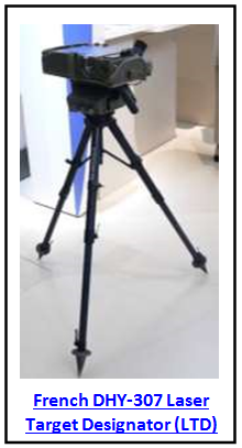
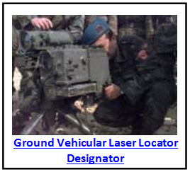
The laser target designator (LTD) is the next step in laser evolution. The LTD can guide semi-active homing bombs, artillery, naval gun rounds, mortar projectiles, rockets, and ATGMs directly onto their target. The seeker on the munitions directs the round onto the “laser splash” aimed on the target. Some LTDs, such as the Russian 1D26, can be carried by a single operator. Most LTDs include a tripod mount with other sub-assemblies such as a built-in LRF or night sight, for easy carrying by a team of two to three soldiers. It is likely that as technology increases, lighter materials will be used to create LTDs making them lighter weight and more easily carried for use by dismounted units. There have even been laser-homing grenades developed for squad ATGLs for well over a decade.
In some LTD-based FCS such as the French DHY-307, the LTD replaces the goniometer for an OP. The LTD FCS may contain such features as an encoded beam to ensure only one hit per target, counter-measures against the enemy looking for lasers, GPS, night sights, and the other sub-components found in a goniometer- based FCS. Most laser munitions can be used with most LTDs. Tier 1 and 2 OPFOR observers will operate the DHY-307 with a designation range of 10 km instead of goniometer-based system. OPFOR recon and AT observers possess the ability to call in laser rounds through man-portable LTDs with a night range out to 5 km with an accuracy of 1 m.
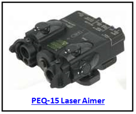
The laser aimer as discussed in the Infantry chapter or laser pointer are used by ground units to shoot direct fire weapons or point out targets to other personnel. The pointers, however, emit light and offer a risk of exposure to a prepared adversary. Thus, the pointers are only used when the fire fight
begins when the using unit possesses fire superiority.
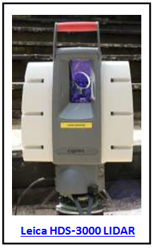
A recent laser technology is the laser locator (also known as the “laser radar” or LADAR or when linked into a weapons fire control system as “optical augmentation) that uses light detection and ranging (LIDAR) to
detect and measure ranges. LIDAR can operate in the active or passive mode. In the active mode, it employs a laser to scan in the observed sector, scanning in a band pattern similar to radar. The aligned IR viewer then looks for IR light generated by laser light reflected by optics and sights. Although the LADAR operating in an active mode creates a narrow laser beam, it limits the beam spread beyond the scanned target. Passive use of LADAR is more difficult because it depends on the use of light close to or behind the viewer in the right frequency with sufficient brightness and the right angularity for the viewer to detect down-range reflections. An example
of LADAR is the Mirage 1200 hand-held “lens detector” with a range up to 1200 m. Laser filters on optics can reduce the effectiveness of detection by LADAR. Reconnaissance vehicles and aircraft employ LADARs for day and night imagery.
For many years, reconnaissance units have detected the enemy through the process of “triangulation.” When 2 or more azimuths are obtained from known locations of a particular target, the target’s location can be determined by drawing the lines on the map to determine where the lines intersect. This intersection is the target’s location. The system previously had some limitations as the time delay from receiving the two locations with azimuths could provide faulty information, especially if the target was on the move. Recent technology can exploit this old methodology. Precise self-location with GPS, computers, digital map displays, and digital data links from different sensors can provide the two locations with the azimuths in a matter of seconds, providing both sensors are aimed at the same target.
Acoustic sensors are also found on the battlefield including multi-directional microphones, directional microphones, sound-ranging arrays, vehicle arrays, which intersect azimuths to locate sound sources including guns, helicopters, and combat vehicles. Artillery sound-ranging systems include the Russian AZK-5 and AZK-7, Swedish Soras 6, and the British HALO all use microphones digitally linked to automated processors for rapid calculation of enemy firing locations. Sensitive microphones on various Israeli Helispot systems, including autonomous acoustic vehicles, enable them to detect and locate enemy helicopters in flight. Man-portable Air Defense Systems (MANPADS) units also use acoustic sensors to determine target locations.
The military continues to find new applications for radar systems, whether they are battlefield surveillance systems mounted on tripods, carriages, weapons, vehicles, aerial platforms, or even trees. New technologies such as miniaturization, millimeter-wave (MMW), improved power supplies, links to laptop computers offer other new applications. Compact radars such as the Fara-1 offer man-portable carrying capability and attachment to weapons, such as automatic grenade launchers (AGL) for fire direction. Slightly larger systems include the Thales Squire two-man radar system with a 24 km operating range that is portable in packs. Tripod-mounted radars such as the Credo-1E can link to digital nets with the ability for easy emplacement or displacement.
The major disadvantage of radar is the system actively emits a signal the enemy can locate through Electronic Warfare (EW) or other systems making the radar vulnerable to attack. Squire is a low probability of intercept (LPI) radar due to its extremely low peak power. Other LIP features include phased array with lower power levels for detectors, reduced side lobes, and operating frequencies outside of most radar intercept system bandwidths. The most common frequency bands for land radar systems have been the I and J bands. In recent years, new radar technologies have been field to add LIP features to reduce intercept vulnerability. Airborne radar such as Horizon use moving target indicator (MTI) and synthetic aperture radar (SAR), and Doppler processing with secure stand- off for missions. MMW radars (30+ GHz) offer precise acquisition and fire control, compact size antennas, and lower signal detectability.
Two other technology trends are on the rise—remote sensors and robotic sensors. Remote sensors are generally immobile, although they may be able to change their field of view in order to see as required. A simple remote sensor is a side-attack mine, such as an anti-tank disposable grenade launcher placed along an expected advance for vehicles and linked to an autonomous acoustic sensor unit, such as AJAC. As the enemy approaches, usually along a road, the device will launch a grenade, thus audibly signaling the vehicle’s approach. Robotic sensors can relocate to perform their mission. Civilian applications have led to a wide variety of remote cameras, remote actuators on robotic systems, and the use with unattended ground sensors including acoustic, IR, seismic, tripwire-
electronic, and magnetic. Key technology constraints include detectability shortfalls, power supply and battery limitations, and signal transmission inadequacies, but the issues are in the process of being resolved. Use of fused sensors means more accurate, timely, and complete reports. Rechargeable batteries, acoustic.IR wake-up, miniaturization, and increased sensor sensitivity all make the use of remote sensors and sensor suites practical as well as marketable.
The British Radamec 1000L system is an example of a remote camera with limited operator presence to detect targets. Other applications include cameras tethered from concealed vehicles and operated through the vehicle power system. New technologies include passive IR scanning cameras with auto-track and alert algorithms such as the French Sirene or British ADAD IR units emplaced on the battlefield to link into sensor nets and monitor sensitive avenues of approach and unit flanks. Early systems include air defense sensors such as ADA, Sirene, or the hand-held Swedish IRS-700. A tethered aerostat balloon can hold a remote camera platform to increase surveillance beyond the line-of-sight. The Israeli TAOS system uses a gimbaled, stabilized, multi-sensor platform with a CCD and thermal camera for day or night use. Radar and laser illuminator applications are optional with the ground station mounted on a trailer. Ground forces are also adapting commercial camera network technologies to create a surveillance camera network that can monitor wide areas on the battlefield. These systems include the CELTICS, TACS, and Gamma 2000—all produced by Israel.
The use of an unattended ground sensor (UGS) by the US dates back to the Vietnam War where the UGS units were placed to detect enemy presence and movement. Some of these sensors were “break-wire” that generated a signal when broken. While the most common UGS is acoustic, other UGS units can monitor seismic, magnetic, infrared, or RF activity. Some UGS units can sleep to save energy and the size can vary from a few centimeters to a few inches in size. Relay systems may be required to forward the signal to the monitoring station. By analyzing the location and pattern of signals, the operator is cued to initiate additional battlefield surveillance activities in selected areas. Examples of UGS units include the Thales Miniature Intrusion Sensor (MIS) and Rafael. Current technology reduces false alarms such as from animals wandering in the area. Emplacement is important as if placed in too open of an area, the UGS can be seen. If placed in an urban or defilade position, the signal may not reach the monitoring station. Larger UGS units may be placed at road junctions, river crossing sites, and other important locations. Examples of the larger UGS units include the ATE UGS, Steel Eagle, Gateway, and Boden- Sensor-Ausstattung (BSA). The Thales CLASSIC 200 has been sold t over 39 countries for military, border control, police, and commercial purposes with a complete network with monitor, acoustic, cameras, and other sensors. Possible roles for the UGS include perimeter protection, route monitoring, and point surveillance. Emerging UGS technologies include linking to other sensors, mine activation, remote weapons system operation, and autonomous cueing to conduct precision targeting. A subset of the UGS is the remotely-delivered sensor that delivers reconnaissance rounds through a weapons system such as artillery or mortars. These rounds, once fired and activated, can provide target location, acquisition, and post-mission battle damage assessment. Cameras provide a low-cost method to obtain immediate view beyond the line-of-sight, over the hill, or behind the foliage, with a reduced risk of being seen. The Israeli IMI recently debuted a Refaim rifle grenade containing a camera that can transmit pictures back to the launching unit as the round descended on its target. A 40-mm under-barrel rifle grenade launcher can fire the Israeli Firefly that transmits video and sound back to a digital radio and laptop computer. In addition to their anti-tank role, fiber-optic ATGMs can use their camera to provide video footage for analysis by reconnaissance units.
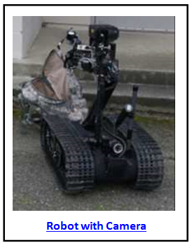
Robotic sensors consist of single or multiple sensors mounted on robots or unmanned ground vehicle (UGV) chassis. Previous applications include the exploration of the ocean floor, other planets, and inaccessible areas
such as caves or volcanoes. The police often uses a robotic sensor for surveillance in hostile situations as well as examining contamination areas such as the Chernobyl nuclear plant. A military version is the tracked Matilda with a day TV camera used in Afghan caves, clearing minefields, and checking for potential IEDs. The OPFOR can use robotic sensors for surveillance and patrols in urban or open terrain to reduce troop vulnerability. A simple application is to use robots controlled from reconnaissance vehicles or nearby personnel. A robotic chassis features EO viewers for guidance and surveillance, such as a TV camera with an RF or cable link; GPS in-view readouts; a thermal or II night channel; and LRF. A robot can carry other sensors including acoustic microphones, NBC samples, radar, or weapons. Other robotic examples include the British tracked Wheelbarrow mine detection system or the Giant Viper wheeled line charge launcher vehicle that tows its own charge trailer. The German company, Telerob, produces tracked robots for industrial, police, and military applications. The Russian SPC robot can employ a number of sensors.
The earliest robotic sensors on the modern battlefield were unmanned aerial vehicles (UAV). See Volume 2 for additional information on UAVs. UAVs can perform pre-programmed (drone) or operator control (remotely piloted vehicle—RPV) missions. The on-board TV camera and its ability to transmit the images to a ground station are the core of the UAV mission. In the last few years, unmanned combat aerial vehicles (UCAV) have appeared to attack located targets. A UAV ground station can consist of only a notebook computer or PDA as a terminal. Due to the high cost of airplanes and the training required to become a proficient pilot, UAVs are an excellent way to work through budget constraints and lack of an efficient manned air force. Recent or expanded technology for UAVs include the following:
- Man-portable UAVs are light weight and can be carried in a backpack and launched by hand such as the German Carolo, Russian Pustelga, or French K100.
- Micro-aerial Vehicles (MAV) use radio-control (RC) model plane technology where some of these are not larger than a man’s hand.
- Improvised UAVs using RC aircraft.
- Vehicle/robotic launch UAVs including canister launchers such as the Israeli Skylite UAV or the UAV the French are looking for their next LeClerc tank upgrade.
- Weapons-launched UAVs such as the Russian R-90 300- mm launched by the 9A152-2 MRL can loiter for 30 minutes while transmitting imagery to an artillery command and reconnaissance vehicle (ACRV).
- LTD UAV where the UAV substitutes as the laser designated in lieu of a soldier or vehicle.
Battlefield monitoring systems require the use of cable links or RF data transmission equipment, and display arrays such as those found in vehicles modified into ground stations. These systems can fuse various technologies, including commercial equipment, together to obtain the best situational awareness possible for the user.
Technology limitations will continue to challenge reconnaissance operations, but solutions will be found. Commercial applications will continue to cross over into the military as forces with limited budgets will continue to use off-the-shelf technology for military purposes. The OPFOR will supplement new technology with low technology to conduct their reconnaissance operations. Innovative military forces can use niche technologies and aggressive manned reconnaissance units to conduct battlefield surveillance operations. The battlefield surveillance networks will consist of personnel, organic sensors, vehicles, UGS, remote sensors, UAVs and any other reconnaissance assets available. Effective equipment, sound organization and planning, commitment to the OE variables, and effective reconnaissance tactics can enable the OFPRO to gain greater situational awareness within their operational area, and to challenge enemy capabilities to achieve tactical surprise.
